How to Build a Transparent DIY Potentiometer for Electronics Education
Introduction
Understanding how a potentiometer works is a fundamental step in learning electronics. While most seasoned makers are comfortable with these variable resistors, beginners often struggle to grasp their inner workings. This is where building a transparent DIY potentiometer shines as an educational tool. The project you see here, originally crafted by [DiscoLapy], exposes every component so that students and hobbyists can see exactly how turning the knob changes resistance. By using everyday materials like a pencil, paper, and a 3D-printed housing, you create a fully functional device that teaches the core principle of variable resistance. Not only is it affordable, but it also makes the invisible process visible – perfect for classrooms, workshops, or self-study.

In this guide, you will learn to assemble your own see-through potentiometer from scratch. We will walk you through each step, from gathering materials to testing the final unit with an LED. By the end, you’ll have both a working component and a deeper intuition for how potentiometers control current flow.
What You Need
Before diving in, collect these items. Most are household or easily sourced from a hobby store.
- 3D printed base and knob – Files available from [DiscoLapy] or design your own. The base has a circular recess for the paper track and a central pivot for the knob.
- Piece of paper or cardstock – Cut to fit the base. This will become the resistive track.
- Standard graphite pencil – No. 2 or similar. Graphite is conductive and will serve as the resistive material.
- Conductive metal contacts – Thin metal strips or wire (e.g., copper tape, brass strips, or paper clips). Two fixed contacts and one moving wiper.
- Small screw or pin – To attach the wiper to the knob and ensure electrical connection.
- Multimeter (optional) – For testing resistance values.
- LED and resistor (around 220 Ω) – For a simple demo circuit to see resistance change in action.
- Battery (e.g., 9V) and wires – To power the demonstration.
- Glue or tape – For securing the paper and contacts.
- Scissors or craft knife – For cutting paper.
Step-by-Step Instructions
Step 1: Prepare the 3D Printed Parts
First, ensure your 3D printed base and knob are clean and free of support material. The base should have a shallow circular well where the paper track will sit, and a center hole for the knob’s axle. The knob should fit snugly over that axle. Sand any rough edges lightly. If you don’t have access to a 3D printer, you can carve a similar shape from wood or thick cardboard, but 3D printing gives the most consistent results.
Step 2: Cut and Secure the Paper Track
With scissors or a craft knife, cut a ring-shaped piece of paper that matches the diameter of the base’s well. The ring should be wide enough (about 1–2 cm) to allow a good graphite coating. Place the paper ring into the base and fix it with a tiny dab of glue or double-sided tape so it doesn’t shift during construction.
Step 3: Apply the Graphite Resistive Layer
Using a soft pencil (graphite), heavily shade the entire surface of the paper ring. The goal is to create a uniform, dark coating. Press firmly and fill every gap. The denser the graphite, the lower the resistance. For best results, shade in multiple directions—overlapping strokes ensure even coverage. Test with a multimeter (touch the probes at two points on opposite sides of the ring) to confirm conductivity. Typical resistance between ends might be anywhere from a few hundred ohms to several kilo-ohms, depending on graphite density. Tip: The resistance value isn’t critical; what matters is that it is uniform along the track.
Step 4: Install the Fixed Contacts
Two fixed contacts will connect to the resistive track at the ends of the paper ring. Cut two small strips of conductive metal (copper tape works well). Place one at the “start” of the ring and one at the “end” (approximately 180 degrees apart). Press them down onto the graphite-coated paper so they make good electrical contact. Secure with a drop of glue if needed. These contacts will serve as the potentiometer’s terminals 1 and 3 (the outer pins). Run wires from these contacts to the outside for easy connection later.
Step 5: Prepare the Wiper Assembly
The wiper is the moving contact that slides along the track. Take a small piece of conductive metal (e.g., a bent paper clip or a strip of brass) and attach it to the underside of the 3D printed knob. The wiper should extend outward enough to touch the graphite track when the knob is placed on the base. Use a small screw or pin to fasten the wiper to the knob – ensure the wiper is electrically connected to the screw head. This screw will also act as the movable terminal (the center pin of the potentiometer).
Step 6: Assemble the Knob and Base
Place the knob onto the base’s central axle. The wiper should now rest gently on the graphite track. Rotate the knob through its full range. The wiper should maintain contact with the track without scraping too hard. If it lifts off, adjust the wiper angle slightly. Once satisfied, secure the knob with a retaining clip or a nut if your 3D design allows. The wiper must be able to turn freely but still press against the graphite.
Step 7: Connect the Wiper Wire
Solder or clip a wire to the screw head or the wiper’s metal base. This wire will serve as the center terminal of the potentiometer. Route it out of the base alongside the wires from the fixed contacts. You now have three wires: left fixed, wiper center, right fixed.
Step 8: Test with a Multimeter
Set your multimeter to measure resistance (ohms). Connect the probes to the left fixed contact and the center wiper wire. Rotate the knob slowly from one side to the other. You should see the resistance change smoothly from near zero (when the wiper is close to the left contact) to a maximum (when it’s far away). Repeat with the right fixed contact and center wire – the resistance should increase as you move away from that contact. This confirms your potentiometer is working.
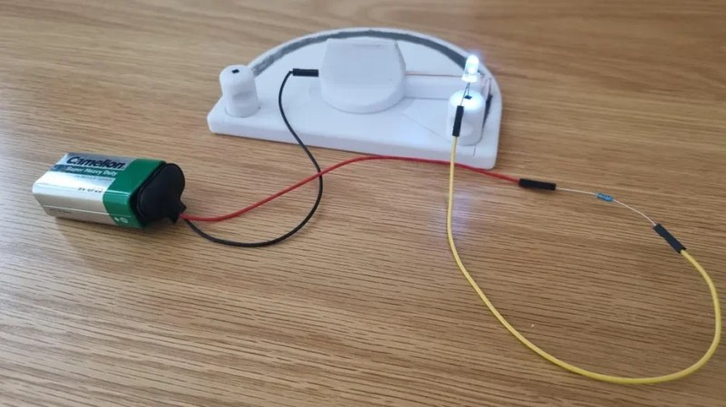
Step 9: Create a Demonstration Circuit
To see the effect in action, build a simple series circuit: battery positive → current-limiting resistor (220 Ω) → LED (anode) → center wire of your potentiometer → one of the outer wires → battery negative (or ground). When you turn the knob, the LED will brighten and dim as the resistance changes. This visual feedback makes it crystal clear how a potentiometer controls current. Tip: Use a resistor to protect the LED from burning out when the potentiometer is at minimum resistance.
Tips for Success
- Graphite quality matters: If the resistance is too high or erratic, try a softer pencil (e.g., 2B or 4B). More graphite means lower resistance and smoother control.
- Keep the wiper clean: Dust or graphite debris can cause intermittent contact. Wipe the track with a clean cloth after assembly.
- Experiment with track shape: A full circular track gives 270–300 degrees of rotation. For a linear potentiometer, use a straight strip of graphite and a sliding wiper.
- Use as a teaching tool: Label the three terminals (A, B, C) and explain that turning the knob changes the resistance between A-C and B-C. This hands-on project complements textbook lessons.
- Encourage customization: Let learners paint or decorate the base. A visually appealing tool is more memorable.
- Expand the lesson: Show how this simple device is used in volume controls, dimmers, and sensor circuits.
- Safety note: This project uses graphite and paper – it is not meant for high-power circuits. Maximum voltage around 9–12V is safe.
Jump to step 1 | Jump to step 9 (These anchor links are placeholders; in actual HTML they would point to the respective headings by id – ensure each step heading has an id like step1, etc.)
Related Articles
- How to Detect and Prevent Reward Hacking in Reinforcement Learning
- How We Uncovered a Hidden ClickHouse Slowdown in Our Petabyte-Scale Billing System
- New AI Agent Automates Open-Source Intelligence Investigations, Eliminates Manual Pivots
- Empowering Educators: ISTE+ASCD Announces 2026-27 Voices of Change Fellows
- Why Are Girls Losing Ground in Math? Insights from the Latest Global Study
- 10 Key Revelations from Elon Musk's Court Testimony on xAI's Use of OpenAI Models
- 10 Key Insights into Reinforcement Learning Without Temporal Difference Learning
- How to Use Coursera’s Gender Gap Data to Drive Women’s Participation in GenAI Skills